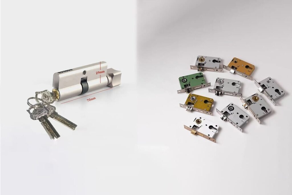
How to Install Door Locks?
To install door locks correctly, I first treat the job as a product-fit check, not only a screw-and-replace task. Many door factories lose time when a lock body fits the cavity but the cylinder, handle spindle, latch direction, or strike plate does not align.1 The solution is to confirm the full Euro-standard mortise lock system before assembly.
To install door locks, confirm the lock body model, center distance, backset, faceplate size, door thickness, cylinder length, handle hole position, latch direction, and strike alignment before final fixing. Then remove the old hardware, fit the new lock body, connect the cylinder and handle set, test operation with the door open, and adjust the strike before closing the door.
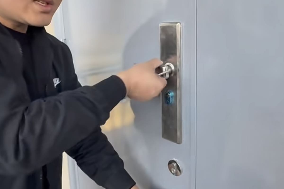
In my work with architectural door hardware, I have learned that installation problems usually start before installation begins. A buyer may order the right-looking lock, but the door opening, cylinder, handle set, and strike plate may not match. So, I will walk through the process from a manufacturer’s perspective.
What should you check before you install door locks?
Before you install door locks, the biggest risk is assuming that similar-looking mortise locks are interchangeable. That assumption can cause wrong hole positions, loose handles, blocked cylinder rotation, or a latch that misses the strike plate. A short parameter check prevents expensive rework.
You should check the center distance, backset, lock body model, faceplate size, door thickness, cylinder length, handle spindle size, handle hole position, latch direction, and strike plate position before installation. For Euro-standard mortise locks, always compare these values against the actual product drawing and door machining drawing.2
Start with the lock body parameters
When I review customer drawings for Euro-standard mortise locks, I usually focus on a few dimensions first. These dimensions decide whether the lock body, cylinder, and handle can work together.
Common examples include:
| Parameter | What it affects | Common examples to verify |
|---|---|---|
| Center distance3 | Distance between handle follower and cylinder center | 72mm or 85mm |
| Backset4 | Distance from faceplate edge to handle/cylinder center line | Often linked to lock model |
| Lock body model | Door application and internal structure | 5572, 6072, 6085 as examples |
| Faceplate size | Fit into door edge routing | 24×235mm as a common example |
| Door thickness5 | Cylinder length and screw selection | Must match project requirement |
| Handle spindle | Handle transmission | Must match follower size |
| Cylinder length | Equal or offset cylinder projection | Must match door + escutcheon/panel thickness |
These are common market examples, not universal rules. I always recommend checking the supplier’s technical drawing, because one factory’s 6072 lock body may not match another factory’s faceplate, case depth, or internal structure exactly.
Why “fits into the hole” is not enough
A lock body can slide into the mortise pocket and still fail in daily use. This is one of the most common misunderstandings I see in bulk door assembly.
A correct installation needs the full movement chain to work:
- The handle must rotate the follower smoothly.6
- The latch must retract fully and return cleanly.
- The cylinder cam must drive the deadbolt without rubbing.7
- The faceplate must sit flat on the door edge.
- The strike plate must receive the latch and deadbolt without forcing.
- The door must close naturally without lifting, pushing, or pulling.
If one point is wrong, the user may feel a heavy handle, poor spring return, noisy closing, or cylinder jamming. In a single home, that is annoying. In a door factory or wholesale batch, that becomes an after-sales problem.
A pre-installation checklist for buyers and factories
Before you install door locks in bulk, I suggest making a simple approval checklist:
- Confirm the door machining drawing against the lock drawing.
- Confirm the handle set drawing against the lock follower and fixing holes.
- Confirm the cylinder type and length against door thickness and trim thickness.
- Confirm the strike plate against frame material and door gap.
- Confirm the opening direction and latch direction.
- Confirm finish, screws, spindle, accessories, and packaging list.
- Approve one sample set before mass assembly.
This process is not slow. It is usually faster than correcting hundreds of doors after production.
How do you measure the door before you install door locks?
Measurement looks simple, but poor marking is one of the fastest ways to create a bad lock installation. If the handle center is too high, the cylinder hole is off-center, or the lock case depth is underestimated, the installation may look acceptable but operate poorly.
To measure before you install door locks, mark the handle centerline, cylinder centerline, backset, lock case depth, faceplate length, faceplate width, and strike position. Use the lock supplier’s drawing as the reference. Then compare the door thickness, door edge routing, and frame position before cutting or drilling.
Use the product drawing as the main reference
For Euro-standard mortise locks, the product drawing is more reliable than visual comparison. The drawing should show:
- Lock case height and depth
- Faceplate width and length
- Backset
- Center distance
- Follower size
- Cylinder hole position
- Screw hole positions
- Deadbolt and latch positions
- Strike plate dimensions
In our factory work, I often see installation-fit issues when a customer replaces one lock model with another based only on the front faceplate. The faceplate may look similar, but the internal case depth or hole position may be different. That small difference can affect drilling, spindle alignment, and cylinder operation.
Key measurements for Euro-standard mortise locks
Here is a practical measurement table I use when discussing lock matching with door manufacturers:
| Measurement point | Why it matters | Risk if wrong |
|---|---|---|
| Door thickness | Determines cylinder length and screw length | Cylinder protrudes too much or sits too deep |
| Center distance | Aligns handle and cylinder holes | Handle or cylinder cannot fit |
| Backset | Locates handle and cylinder from door edge | Holes shift too close or too far from edge |
| Lock case depth | Determines mortise pocket depth | Lock body cannot sit fully |
| Faceplate size | Controls door edge routing | Faceplate sits proud or leaves gaps |
| Handle fixing holes | Matches lever rose or long plate | Panel screws conflict with lock body |
| Strike location | Aligns latch and deadbolt with frame | Door cannot close smoothly |
Marking should follow function, not guesswork
When a production team prepares doors, I prefer that they mark from fixed reference lines. The door edge and finished floor line are typical references, but the exact method depends on the factory process and project drawing.
A good marking process usually includes:
- Mark the lock height according to the project requirement.
- Mark the lock body centerline on the door edge.
- Mark the backset line on both door faces.
- Mark the handle follower position.
- Mark the cylinder position.
- Confirm the lock case pocket depth.
- Confirm the faceplate recess area.
- Transfer latch and deadbolt positions to the frame for strike alignment.
For B2B production, I suggest making a drilling template only after the sample lock set is approved. This is important because a template based on an unverified lock body can multiply one mistake across an entire production run.
My practical rule is simple: measure twice, compare with the drawing once more, and only then machine the door.
This rule sounds basic, but it helps reduce wrong openings, especially when a buyer changes suppliers or upgrades from an interior lock body to an entrance lock body.
How do you remove the old lock before fitting a new mortise lock?
Old lock removal can create new problems if the installer damages the door edge, loses reference points, or assumes the existing opening matches the new lock. The old lock may also hide wear, frame movement, or previous drilling errors.
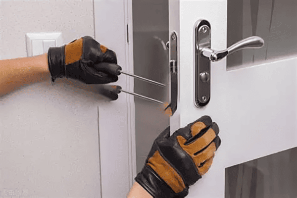
To remove an old mortise lock, take off the handles or panels first, loosen the cylinder fixing screw, remove the cylinder, unscrew the faceplate, and slide out the lock body carefully. Then inspect the existing mortise pocket, handle holes, cylinder hole, door edge, and strike plate before fitting the replacement lock.
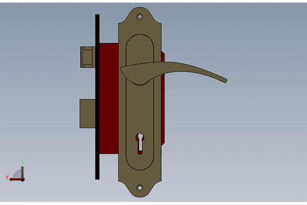
Remove accessories in the correct order
For a Euro-standard mortise lock set, I usually think of the hardware in layers. The outside visible parts come off first, and the lock body comes out last.
A common removal order is:
Remove lever handles or panels.
Loosen grub screws or fixing screws. Keep the spindle aside.Remove escutcheons or long plates.
Check whether the screws pass through the door or fix into one side only.Remove the cylinder fixing screw.
This screw is usually on the lock faceplate and holds the profile cylinder.Turn the key slightly and pull out the cylinder.
The cam must align with the cylinder body before it can slide out.Unscrew the lock faceplate.
Support the lock body while removing screws.Slide out the lock body.
Do not force it if the pocket is tight or painted over.
This process helps protect the door and keeps the existing opening readable.
Inspect the old opening before choosing the new lock
The old opening is not automatically correct. It may have been modified on-site, enlarged by hand, or damaged during years of use. Before you install door locks as replacements, compare the old opening with the new lock drawing.
Look for these issues:
- The mortise pocket is too shallow for the new lock case.
- The faceplate recess is too short or too wide.
- The handle hole does not align with the new follower.
- The cylinder hole is too high, low, or small.
- The door edge is cracked around screw holes.
- The old strike plate position does not match the new latch.
- Paint, veneer, or sealant blocks the faceplate from sitting flat.
For a single door, a skilled installer may correct small differences. For a door factory, these differences should be controlled through approved machining drawings and sample testing.
When replacement becomes a specification issue
I often see buyers ask, “Can your lock replace our current lock?” My answer is usually: “Please send the drawing, door thickness, and lock photos with measurements.” That answer may sound cautious, but it prevents mistakes.
Replacement depends on matching several items:
| Replacement item | Must match or be adjusted |
|---|---|
| Lock body | Case depth, faceplate, backset, center distance |
| Cylinder | Profile type, cam, length, key function |
| Handle | Spindle, fixing centers, rose or plate design |
| Door | Existing holes, edge pocket, thickness |
| Frame | Strike plate position and frame preparation |
If you are buying for a project or batch order, I recommend approving a replacement sample before confirming a container or large purchase order. A small sample fee is usually much cheaper than field complaints.
How do you install door locks with the correct latch direction and cylinder alignment?
Many installation failures happen because the latch direction or cylinder cam position is wrong. The lock may enter the door pocket, but the latch faces the wrong way, or the cylinder cannot turn the deadbolt cleanly. These problems are easy to prevent with open-door testing.
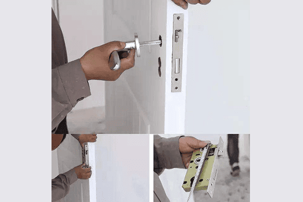
To install door locks with correct latch and cylinder alignment, confirm the door opening direction, reverse the latch if the lock design allows it, insert the lock body squarely, align the profile cylinder cam, tighten the cylinder screw gently, and test latch retraction and deadbolt movement before fixing the handles fully.
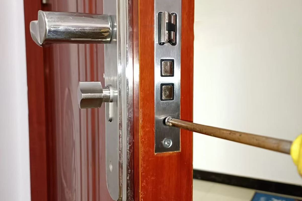
Confirm opening direction before final assembly
Door opening direction affects latch orientation. A beveled latch must meet the strike plate correctly when the door closes.8 If the bevel faces the wrong way, the door may not latch without pushing the handle down.
Before installation, confirm:
- Left-hand or right-hand opening
- Inward or outward swing
- Latch bevel direction
- Whether the latch is reversible
- Whether the lock body is universal or handed
Not every lock body reverses in the same way.9 Some designs allow quick latch reversal. Others require a specific handed lock. I recommend checking the supplier’s instruction sheet or product drawing before reversing anything.
Fit the lock body without forcing it
When you install door locks, the lock body should enter the mortise pocket straight and sit flat against the door edge. If the installer has to hammer the lock into place, the pocket is likely too tight, misaligned, or blocked by debris.
A forced lock body can cause:10
- Internal case deformation
- Heavy latch movement
- Poor deadbolt throw
- Faceplate bending
- Noise during operation
- Shorter product life
The faceplate should sit flush with the door edge. The screws should hold the faceplate firmly, but they should not twist the lock body out of position.
Align the cylinder cam correctly
For Euro profile cylinders, the cam position matters. The cylinder will not slide through the lock body if the cam sticks out at the wrong angle. Usually, the key is turned slightly to align the cam with the cylinder body.
After the cylinder is inserted:
- Install the cylinder fixing screw from the faceplate side.
- Tighten it until secure, but do not overtighten.
- Turn the key with the door open.
- Check that the deadbolt extends fully.
- Check that the deadbolt retracts fully.
- Remove the key only after normal rotation is confirmed.
If the cylinder feels rough, do not solve the problem by applying more force.11 Check cylinder length, cam compatibility, lock body alignment, and screw pressure. A fixing screw that is too tight or angled can sometimes affect cylinder movement.
Test before the door is closed
I always prefer open-door testing before the first closing test. This avoids a situation where the deadbolt extends into a misaligned strike and traps the door.
Test in this order:
- Press the latch by hand.
- Turn the handle spindle or handle.
- Turn the key to extend the deadbolt.
- Turn the key to retract the deadbolt.
- Check spring return.
- Check that the latch returns fully.
- Check that no screw contacts moving parts.
Only after these tests should you close the door gently and test the strike alignment.
How do you connect handles, spindle, and panels when you install door locks?
A lock installation can fail even when the lock body and cylinder are correct. If the spindle is too short, the handle follower is mismatched, or the fixing screws pull the panels out of line, the user will feel loose movement or heavy operation.
To connect handles when you install door locks, insert the spindle through the lock follower, fit both lever handles or panels squarely, align fixing screws with the lock and door preparation, tighten evenly, and test handle return. The spindle and handle set must match the mortise lock follower and door thickness.
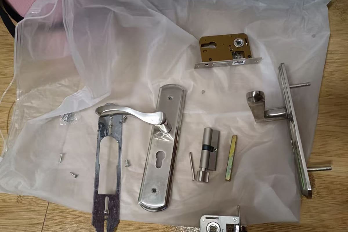
Handle transmission depends on spindle fit
The spindle transfers hand force from the lever handle to the lock follower. If the spindle does not fit well, the handle may feel loose, noisy, or unstable.
Common spindle-related issues include:
- Spindle too short for the door thickness
- Spindle too long and pushing against the opposite handle
- Wrong spindle section for the lock follower
- Loose grub screw contact
- Poor alignment between handle and lock body
- Handle spring fighting against lock spring
In hardware production, I pay close attention to accessory matching because the lock body alone does not create the user experience. The handle, spindle, spring, screws, and lock follower all work as a system.
Rose handles and long plates have different risks
Euro-standard mortise locks may be used with lever handles on rose, escutcheons, or long plates. Each design has different installation risks.
| Handle style | Main advantage | Installation risk |
|---|---|---|
| Lever on rose | Flexible design and modern appearance | Fixing screws may conflict with lock case |
| Lever with escutcheon | Separate handle and cylinder cover | Alignment must be clean between two parts |
| Long plate handle | Covers more door surface | Plate holes must match lock centers |
| Security handle set | Stronger outside protection | Door thickness and cylinder projection matter more |
For long plate handles, the center distance is especially important. A lock with 72mm center distance needs a matching plate. A lock with 85mm center distance needs a different matching layout. These numbers are common examples, and buyers should verify the actual drawing.
Tighten evenly and test movement
When fixing panels or handles, tighten screws gradually. If one side is tightened fully before the other side is seated, the handle may pull out of square. That can create friction in the spindle or follower.
A simple handle test includes:
- Push down the handle slowly.
- Release it and check spring return.
- Repeat from both sides.
- Turn the key while holding the handle free.
- Check that the handle screws do not loosen movement.
- Confirm that the latch retracts completely.
The handle should not scrape the rose, plate, or door surface. The return should feel stable. The user should not need extra force to open the door.
Why factories should approve complete sets
For bulk procurement, I strongly recommend testing the complete lock set, not separate components only. A buyer may source the lock body from one factory, the cylinder from another, and the handle from a third. That can work, but only if the technical matching is controlled.
Before mass production, approve:
- Lock body sample
- Cylinder sample
- Lever handle sample
- Spindle and screws
- Strike plate
- Door thickness range
- Finish sample
- Packaging and accessory list
This is where one-stop sourcing can reduce risk, but the main point is not the sourcing model. The main point is system compatibility.
How do you test strike alignment after you install door locks?
The final risk appears at the door frame. The lock may work perfectly with the door open, but it may jam when the latch and deadbolt meet the strike plate. This issue is common when door gaps, hinges, or frame preparation are not controlled.
After you install door locks, test strike alignment by closing the door slowly, checking latch entry, turning the key without lifting or pushing the door, and confirming full deadbolt throw. Adjust the strike plate, frame preparation, or door alignment if the latch or deadbolt rubs, binds, or misses the opening.
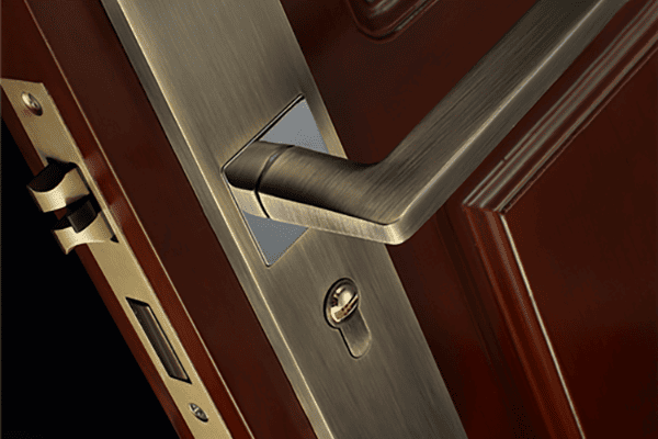
Open-door success is only the first test
I like to separate lock testing into two stages:
- Open-door test: Tests the lock set itself.
- Closed-door test: Tests the lock, door, hinges, frame, and strike together.
Many installers stop after the open-door test. That is not enough. The strike plate is part of the locking system.12 If the strike position is wrong, users may blame the lock even when the lock body is not the cause.
Check latch and deadbolt movement at the frame
Close the door slowly without using the handle. Watch how the latch contacts the strike plate. It should slide into the latch opening without strong impact.
Common strike alignment causes
Strike problems often come from the door and frame, not only the lock.
| Symptom | Possible cause | What to check |
|---|---|---|
| Latch hits strike edge | Strike too high, low, or shallow | Latch mark and strike opening |
| Deadbolt rubs | Frame pocket misaligned | Deadbolt throw path |
| Door must be lifted | Hinge sag or poor frame alignment | Door gap and hinge fixing |
| Key feels heavy only when closed | Strike resistance | Frame pocket depth |
| Door rattles after closing | Strike opening too loose | Latch engagement and gasket pressure |
Bulk production testing
For bulk orders, I recommend a documented testing process. It does not need to be complicated.
A practical factory test can include:
- First-piece inspection before batch assembly
- Random inspection during production
- Handle return test
- Cylinder rotation test
- Deadbolt throw test
- Latch closing test
- Strike plate fit test
- Surface finish check
- Accessory quantity check
If the order involves CE-marked or fire-rated hardware, buyers should verify certificates, product scope, test reports, and project requirements with qualified professionals or local authorities. I can speak from a manufacturer’s product-matching perspective, but application-specific compliance decisions should be confirmed against the project standard.
How should B2B buyers plan before they install door locks in bulk?
Bulk installation changes the risk level. A small mismatch on one door is a repair. The same mismatch across 500 doors is a cost, delivery, and reputation problem. Buyers need to control specifications before placing large orders.
Treat installation as part of supplier evaluation
A good supplier evaluation should include:
- Product drawings with clear dimensions
- Stable lock body models
- Matching cylinder and handle options
- Surface finish consistency
- Batch production capability
- Inspection process
- Packaging protection
- Spare parts and after-sales support
- Certification documents for buyer verification
Sample approval should copy real use
A sample should not sit in a drawer. It should be installed on the real door construction or a test door that matches the project.
The sample test should confirm:
- Door thickness compatibility
- Lock case fit
- Faceplate fit
- Handle hole alignment
- Cylinder length and projection
- Latch direction
- Strike plate alignment
- Handle return
- Finish appearance
- Accessory completeness
Batch consistency matters
For wholesalers and door manufacturers, consistency is often more important than one perfect sample. The production batch must match the approved sample in dimensions, finish, function, and accessories.
Important quality control points include:
| QC point | Why it matters for bulk buyers |
|---|---|
| Raw material control | Supports stable strength and machining |
| Lock body assembly inspection | Reduces operation failure |
| Surface finish control | Keeps batch appearance uniform |
| Dimension inspection | Protects door machining compatibility |
| Function testing | Confirms latch, deadbolt, and follower movement |
| Packaging inspection | Prevents missing screws, spindles, or cylinders |
Conclusion
To install door locks successfully, I recommend thinking like a manufacturer before thinking like an installer. Confirm the lock body model, center distance, backset, faceplate, cylinder, handle spindle, latch direction, and strike alignment before final assembly. A lock that fits the hole is not enough; the full door hardware system must work smoothly. If you need Euro-standard mortise locks, cylinders, handles, or matching hardware sets for bulk projects, contact SDH Hardware to review drawings, samples, and procurement requirements.
"087100 – DOOR HARDWARE - Facilities and Campus Services", https://fcs.cornell.edu/087100-door-hardware. A general reference on mortise locks describes them as assemblies fitted into a door pocket and operating with coordinated components such as latch bolts, deadbolts, cylinders, handles, and strike plates; this supports the need to check component compatibility, although it does not quantify factory time losses. Evidence role: general_support; source type: encyclopedia. Supports: A neutral source should support that mortise locks are multi-component assemblies whose operation depends on the lock case, cylinder or key mechanism, handles or spindle, latch/bolt, and strike working together.. Scope note: Contextual support only; it does not directly measure time lost in door factories. ↩
"087100 – DOOR HARDWARE - Facilities and Campus Services", https://fcs.cornell.edu/087100-door-hardware. Institutional guidance and standards for mechanically operated locks and latches identify dimensional and functional characteristics as part of hardware specification; this supports the practice of comparing lock drawings with door preparation drawings, although it does not prescribe the article’s exact checklist. Evidence role: general_support; source type: institution. Supports: A standards or institutional source should support that mechanically operated locks and latches are specified through dimensional and functional characteristics, making drawings and measured parameters relevant to installation.. Scope note: Contextual support; the source may define specification criteria rather than the exact workflow. ↩
"Door Knobs & Backset Explained: Sizes & Measuring", https://www.suffolklatchcompany.com/blogs/news/door-knobs-and-backset-explained?srsltid=AfmBOopbQmZ2mij0mjF7Qx0eTsSMU2NwIftTl2m9Icm6cS0DQX-IewZi. Technical lock specifications commonly define the lock centre distance as the spacing between the handle follower and the cylinder or keyhole centre, supporting its use as a matching dimension for handles and plates. Evidence role: definition; source type: institution. Supports: A technical or standards-based source should define center distance or centres as the distance between the handle follower and cylinder/keyhole center in mortise locks.. Scope note: Terminology can vary by region and standard, so the source may use 'centres' or 'PZ distance' rather than the article’s wording. ↩
"Door Knobs & Backset Explained: Sizes & Measuring", https://www.suffolklatchcompany.com/blogs/news/door-knobs-and-backset-explained?srsltid=AfmBOop1v8IB9AZFUTpzVenfyKM8Kb7z4XD0kkNJPniEmbwz5mYbHMAs. A general door-hardware reference defines backset as the distance from the door edge to the centre of the lock or latch mechanism, supporting the article’s treatment of backset as a critical installation measurement. Evidence role: definition; source type: encyclopedia. Supports: A neutral reference should define backset in door hardware as the distance from the edge of the door to the center of the lockset or bore.. ↩
"Euro Cylinder Sizes Explained: 30/30, 35/45, 40/40 and More", https://www.welock.com/blogs/news/euro-cylinder-sizes-explained?srsltid=AfmBOooBAqUhjCPNzE94bNdpb8rN0aH5myGOrAXD5BPeD940NDgLJEFo. Technical guidance on profile cylinders explains that cylinder length is selected according to the total door and trim thickness, supporting the article’s claim that door thickness affects cylinder length and related fastener selection. Evidence role: mechanism; source type: institution. Supports: A source should explain that profile cylinder length is selected according to door thickness and the thickness of trims or escutcheons.. Scope note: The source may directly address cylinder sizing but only indirectly support screw-length selection. ↩
"Mortise lock", https://en.wikipedia.org/wiki/Mortise_lock. Educational material on mortise lock construction describes the follower as the part turned by the handle spindle to retract the latch, supporting the article’s statement that smooth follower rotation is necessary for correct handle operation. Evidence role: mechanism; source type: education. Supports: An educational or technical source should explain that the spindle passes through the follower and transfers handle rotation to the latch mechanism.. ↩
"How does a Euro mortise lock work?", https://www.danddhardware.com/amp/How-does-a-Euro-mortise-lock-work-id3827659.html. A technical reference on cylinder locks explains that the profile cylinder uses a rotating cam or actuator to engage the lock case mechanism, supporting the article’s claim that cam alignment and free movement are necessary for deadbolt operation. Evidence role: mechanism; source type: encyclopedia. Supports: A source should explain that a profile cylinder has a cam or actuator that turns within the lock case to operate the locking bolt mechanism.. Scope note: The source may describe cylinder operation generally rather than the exact lock model discussed in the article. ↩
"Adjusting door strike to fix lock issue", https://www.facebook.com/groups/homemakingtips/posts/1432555254107633/. Educational door-hardware material explains that a beveled latch is shaped to contact the strike plate and retract as the door closes before springing into the strike opening, supporting the importance of correct latch orientation. Evidence role: mechanism; source type: education. Supports: A source should support that spring latches have a beveled face designed to ride over the strike plate and enter the strike opening as the door closes.. ↩
"How to Reverse a Mortise Lockset Handing | Step-by-Step ...",
. Institutional door-hardware guidance distinguishes handed, non-handed, and reversible lock functions, supporting the article’s statement that latch reversal depends on the specific lock-body design. Evidence role: general_support; source type: institution. Supports: A source should support that door locks may be handed, non-handed, or reversible depending on design, and that latch reversal procedures differ.. Scope note: The source may describe categories of handedness rather than catalog every reversal mechanism. ↩"How to Install a Mortise Lock",
. Technical installation guidance for mortise locks states that the lock case should be seated squarely in a correctly sized mortise and that binding or forced fitting can interfere with latch and bolt operation; this supports the article’s warning, although exact failure modes vary by product. Evidence role: mechanism; source type: education. Supports: A technical installation guide should support that mortise locks should fit squarely and not be forced, because misalignment or pressure can interfere with latch and bolt operation.. Scope note: Contextual support; the source may not list every consequence named in the article. ↩"r/DIYUK - Stripped screw head - retaining bolt for Euro Cylinder lock", https://www.reddit.com/r/DIYUK/comments/14jhlxq/stripped_screw_head_retaining_bolt_for_euro/. Technical troubleshooting guidance for cylinder locks notes that rough or binding key operation may result from misalignment, hardware pressure, or incorrect installation, supporting the article’s advice to diagnose the cause rather than apply greater force. Evidence role: mechanism; source type: education. Supports: A source should support that cylinder binding can result from installation alignment, improper screw pressure, or hardware mismatch, and that force should not be used as a remedy.. Scope note: The source may discuss cylinder binding generally rather than Euro profile cylinders exclusively. ↩
"Mortise lock", https://en.wikipedia.org/wiki/Mortise_lock. A general reference defines a strike plate as the frame-mounted metal plate or opening that receives a door latch or bolt, supporting the article’s statement that it forms part of the locking system. Evidence role: definition; source type: encyclopedia. Supports: A neutral source should define a strike plate as the metal plate fixed to the door frame that receives the latch or bolt.. ↩