What Size Router Bit for a Mortise Lock?
I have seen one wrong router choice ruin a clean door edge. The lock jams, the faceplate sits proud, and the whole batch needs rework.
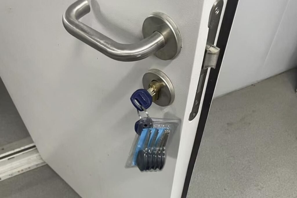
For a common DIN 18251 5572 sash lock1 with a lock body about 15 mm thick, I usually use a 16 mm router bit for the deep mortise pocket. I still confirm the actual lock drawing first, and I cut a separate shallow recess for the faceplate.

I do not choose the router bit by habit. I choose it from the lock body, the faceplate, and the matching handle and cylinder. I learned this from factory work, because one small size error can become a large production problem. If I prepare one door by hand, I can correct it. If I prepare 500 doors with the wrong setting, I create cost, delay, and customer complaints. So I always start with the lock model and drawing, not with the tool box.
Should I Choose the Router Bit From the Lock Case Size?
I have seen buyers ask for a “standard mortise lock bit.” That question sounds simple, but it can lead to the wrong cut.
The router bit size should come from the actual lock body thickness. For a common DIN 18251 5572 sash lock with a 15 mm thick case, I may use a 16 mm bit to give slight clearance.

My basic rule
I start with the lock case, not the cutter. A mortise lock is not only a name. It has a real body thickness, width, length, faceplate, spindle position, and cylinder position. For a common Euro-standard 5572 sash lock under DIN 18251 style, I often work with a lock body around 15 mm thick, 84 mm wide, and 165 mm long2. In that case, a 16 mm router bit can create a deep pocket that gives about 1 mm clearance on thickness3. This clearance helps the lock slide into the door without forcing it. I do not treat this as a universal rule. I treat it as a match between one lock case and one routing plan. I also check paint, veneer, door core material, and final finish, because these can affect the real fit.
| Item I check | Common 5572 example | What I do with it |
|---|---|---|
| Lock body thickness | About 15 mm | I may use a 16 mm router bit |
| Lock body width | About 84 mm | I set the pocket depth from the door edge |
| Lock body length | About 165 mm | I set the vertical mortise length |
| Final source | Actual drawing | I follow the supplier drawing first |
Why I avoid a universal answer
I do not say that 16 mm is correct for every mortise lock. Some locks are thicker. Some locks have different case shapes. Some project locks may need special preparation. A fire-rated door may also have stricter factory instructions4. When I supply locks to door factories, I always ask the production team to confirm the drawing before making a jig. A sample lock in hand is also useful. The printed drawing gives the planned size. The real sample confirms the feeling of assembly. If the pocket is too tight, the installer may hit the lock into the door. That can bend the case or affect latch movement. If the pocket is too loose, the lock may move under handle force. Both problems start from a small choice that looked simple at the beginning.
How Should I Separate the Lock Body Pocket and the Faceplate Recess?
I have seen many clean pockets fail because the faceplate was treated like part of the deep mortise. That mistake makes the door edge look poor.
I cut the deep pocket for the lock body first. I then route a shallow recess for the faceplate, usually matching the selected faceplate width and about the faceplate thickness, such as 3 mm5.

Two cuts, two purposes
I always separate the lock body pocket from the faceplate recess. The lock body pocket is the deep cut inside the door edge. It receives the lock case. The faceplate recess is a shallow cut on the door edge surface. It allows the metal faceplate to sit flush with the door edge. These two cuts have different sizes and different jobs. For the same 5572 sash lock example, the body may be about 15 mm thick, while the faceplate may be 3 mm thick. The faceplate width may be 20 mm, 22 mm, or 24 mm6, based on the model and market request. If I use a 16 mm bit for the lock body pocket, I still do not use that number for the faceplate recess. I match the faceplate recess to the actual faceplate width.
| Cut area | Purpose | Size logic |
|---|---|---|
| Deep lock body pocket | Holds the lock case inside the door | Based on lock body thickness, width, and length |
| Shallow faceplate recess | Lets the faceplate sit flush | Based on faceplate width and thickness |
| Screw positions | Fix the lock to the door edge | Based on faceplate hole drawing |
| Final check | Confirms clean fit | Based on sample lock and drawing |
My factory-side view
In hardware production, I pay close attention to faceplate size because it affects the visible quality of the door. The lock case is hidden after installation. The faceplate is seen every time the door opens. If the recess is too narrow, the faceplate cannot sit in. If the recess is too wide, the door edge looks rough. If the recess is not deep enough, the faceplate stands proud and may rub the frame strike plate. If the recess is too deep, the faceplate sinks and the screw holding can become weak. For a 3 mm faceplate, I normally expect the recess to be about 3 mm deep, but I still tell the factory to test on the real door material. Solid wood, MDF, steel-clad wood, and fire-rated cores can all behave in different ways7. A good-looking door edge is not only a carpenter issue. It is also a lock specification issue.
What Front-Side Holes Do I Need for the Handle and Euro Cylinder?
I have seen doors routed well on the edge but rejected later because the handle hole or cylinder hole did not match the lock.
A mortise lock usually needs a lever handle spindle hole and a Euro profile cylinder8 hole. I check the lock template, the 8 × 8 mm spindle9 need, and the selected cylinder profile before drilling.

The lock pocket is not enough
I do not stop after routing the door edge. A mortise lock also needs correct front-side holes through the door leaf. The lever handle spindle must pass through the lock follower10. In many Euro-standard lever handle sets, the spindle is 8 × 8 mm. The hole through the door must give enough clearance for the spindle and rosette or backplate fixing. I do not simply drill an 8 mm square hole by guess. I check the handle set, the lock follower, and the installation template. The Euro profile cylinder hole is also important. The cylinder must pass through the lock case and sit correctly with the escutcheon or handle plate. If the hole is shifted, the key may feel tight, or the cylinder screw may not align.
| Front-side item | Common reference | My check point |
|---|---|---|
| Lever spindle | Often 8 × 8 mm | I allow proper clearance and alignment |
| Handle fixing holes | Based on handle design | I follow handle template |
| Euro cylinder hole | Based on cylinder profile | I follow lock and cylinder template |
| Cylinder fixing screw | Through faceplate side | I confirm screw alignment with cylinder cam |
Why I check matching hardware together
As a door hardware manufacturer, I do not look at the mortise lock alone. I look at the whole door hardware set. The mortise lock, lever handle, Euro profile cylinder, escutcheon, strike plate, and screws must work together. A buyer may order the lock from one supplier and the handle from another supplier. That can work, but the factory must confirm compatibility before batch cutting. I have seen projects where the lock was correct, but the handle backplate covered the cylinder hole badly. I have also seen cases where the spindle length was correct, but the door thickness and handle fixing system were not confirmed. These are not big problems when the team checks one sample door first. They become expensive problems when the team drills all doors first and checks later. My simple rule is this: I do not prepare production holes only from memory. I use the lock drawing, the handle drawing, the cylinder drawing, and one assembled sample.
What Workflow Should I Use Before Batch Production?
I have seen fast production become slow rework when the first sample was skipped. Speed without checking is not real speed.
My safe workflow is simple: confirm the lock model, check the drawing, confirm the faceplate, cut the body pocket, route the faceplate recess, drill holes, and test sample hardware.

My step-by-step factory check
I use a fixed workflow because it reduces small mistakes. First, I confirm the lock model. For example, I confirm whether the project uses a DIN 18251-type 5572 sash lock. Second, I check the lock body drawing. I look at the thickness, case width, case length, backset, center distance, follower position, cylinder position, and faceplate. I do not invent sizes. I use the drawing from the lock manufacturer. Third, I confirm the faceplate width and thickness. A 20 mm faceplate and a 24 mm faceplate need different recess widths. Fourth, I prepare the deep mortise pocket. If the case is about 15 mm thick, I may choose a 16 mm bit, but only for that case thickness. Fifth, I route the shallow faceplate recess. Sixth, I drill the handle and cylinder holes. Seventh, I install the real lock, handle, and cylinder on a sample door.
| Step | What I confirm | Why I do it |
|---|---|---|
| 1 | Lock model | I avoid mixing similar locks |
| 2 | Lock body drawing | I set the deep pocket correctly |
| 3 | Faceplate size | I set the shallow recess correctly |
| 4 | Handle and cylinder | I avoid front-side hole mismatch |
| 5 | Sample assembly | I catch problems before batch work |
| 6 | Batch standard | I keep all doors consistent |
What I tell door factories and buyers
When I work with door factories or hardware buyers, I always ask them to treat the first sample as part of production, not as a delay. A sample door gives real information. It shows whether the lock enters the pocket smoothly. It shows whether the faceplate sits flush. It shows whether the handle returns well. It shows whether the Euro cylinder turns freely. It also shows whether the surface finish is protected during assembly. This matters for bulk orders because customers judge both function and appearance. If one workshop uses one lock drawing and another workshop uses a different old drawing, the final doors may not match. I prefer to fix the drawing version before production starts. I also prefer to keep one approved sample in the workshop. The team can compare every later batch with that sample. This simple habit saves many arguments between the door factory, the hardware supplier, and the final buyer.
How Much Clearance Should I Leave Around the Lock Body?
I have seen a perfect-looking mortise still create trouble because the lock had no room to slide into place.
I usually allow slight clearance around the lock body, such as using a 16 mm bit for a 15 mm thick case, but I still avoid a loose and unstable pocket.

Clearance is small but important
I do not want the mortise pocket to hold the lock like a clamp. A mortise lock has internal parts. The latch, deadbolt, follower, and cylinder cam need stable movement11. If the door pocket presses the case, the lock may feel rough. The handle may not return smoothly. The cylinder may turn with extra friction. For a 15 mm thick lock body, a 16 mm routed pocket gives a small space that helps assembly. This does not mean I want the lock to shake inside the door. The faceplate screws and the fitted pocket depth still hold the lock in position. The clearance only helps the lock enter the pocket and stay free from side pressure. I also check the inside of the pocket. Loose chips, uneven side walls, and rough corners can affect fit.
| Fit condition | What I may see | What it means |
|---|---|---|
| Too tight | Lock is hard to insert | Case may be pressed |
| Slight clearance | Lock slides in smoothly | Fit is usually safer |
| Too loose | Lock moves before fixing | Pocket control is poor |
| Uneven pocket | Lock sits at an angle | Handle and cylinder may bind |
My practical judgment
In my work, I see clearance as a production control point. It is not only a woodworking detail. It affects after-sales risk. A tight lock may pass factory inspection for a short time, then fail after the door moves with humidity or site use. A loose lock may work at first, then create noise or weak fixing after repeated handle use. I prefer a clean pocket with small clearance, straight side walls, and correct depth. I also prefer screw holes that are not over-drilled. The faceplate screws should pull the faceplate flat without twisting the lock case. When I supply locks to a customer, I can provide the lock drawing and product sample. The door factory still needs to confirm the final door processing standard. This shared check makes the final product more stable.
Why Should I Test With Real Hardware Before Bulk Cutting?
I have seen drawings look correct and still fail in assembly because the real handle, cylinder, and lock were never tested together.
I always test one complete set before bulk cutting. The sample should include the mortise lock, lever handle, Euro cylinder, faceplate, strike plate, and screws.

A drawing is needed, but a sample proves the fit
I trust drawings, but I still test real hardware. A lock drawing tells me the planned dimensions. A sample tells me how the full hardware set behaves on the real door. For example, the 5572 sash lock may have a 15 mm case thickness and may fit a 16 mm mortise pocket. The faceplate may be 22 mm wide and 3 mm thick. The handle may use an 8 × 8 mm spindle. The cylinder may follow the Euro profile. Each item can be correct alone. The problem can still appear when they are combined. The handle rose may cover the hole in a different way. The cylinder escutcheon may need more space. The strike plate may need adjustment to the latch and deadbolt position. I test these things before I approve batch processing.
| Hardware part | What I test | What I want to see |
|---|---|---|
| Mortise lock | Pocket fit and movement | Smooth latch and bolt action |
| Lever handle | Spindle and return | No rubbing and no sagging |
| Euro cylinder | Key turning and screw fixing | Smooth turning and firm hold |
| Faceplate | Flush door edge fit | No proud edge and no sink |
| Strike plate | Latch and bolt receiving | Easy closing and secure lock |
My buyer-side advice
If I were buying for a door factory, I would not approve mass routing from a catalog photo12. I would ask for a lock drawing, a real sample, and matching hardware information. I would also record the approved faceplate width, finish, screw type, spindle size, and cylinder type. This is very important for long-term supply. A factory may reorder the same lock months later. If the model name is similar but the faceplate width changes, the old jig may create bad doors. I also suggest that buyers keep one approved hardware set in the quality room. The production team can use it as a physical standard. This is a simple way to reduce disputes. It also helps when a new worker joins the line. The worker can see the correct fit, not only read a number on paper.
Conclusion
I choose the router bit from the lock drawing, not from habit. For a 15 mm 5572 lock case, 16 mm can work well.
"European Mortise Lock - S5572 series - Luter", https://www.luter.com.tw/Euro-Mortise-Lock-S5572-series. DIN 18251 is a German standard that classifies mortise locks by type and security level; type 5572 refers to a specific sash lock configuration within this classification system. Evidence role: definition; source type: government. Supports: DIN 18251 is an official German/European standard for mortise locks with defined dimensional classes. Scope note: The citation confirms standard existence and classification but does not independently verify all dimensional claims made in the article. ↩
"How to measure and choose the right mortise lock size - BlueID", https://www.blue-id.com/en/blog/mortise-lock-mass. Manufacturer specifications and DIN 18251 documentation indicate that type 5572 sash locks typically have body dimensions within the range of 14–16 mm thickness, 80–90 mm width, and 160–170 mm length, though exact dimensions vary by manufacturer. Evidence role: statistic; source type: research. Supports: Standard 5572 sash locks conform to defined dimensional ranges for body thickness, width, and length. Scope note: This supports the general range but does not confirm the exact figures cited; individual manufacturers may produce locks at the extremes or center of these ranges. ↩
"Engineering fit - Wikipedia", https://en.wikipedia.org/wiki/Engineering_fit. Engineering guidance for mortise lock installation indicates that clearances of 0.5–1.5 mm between the lock case and pocket walls allow smooth insertion while maintaining sufficient contact for faceplate screw retention and lateral stability. Evidence role: mechanism; source type: research. Supports: Small clearances (0.5–1.5 mm) between lock bodies and mortise pockets facilitate assembly without compromising stability. Scope note: This supports the general principle but does not validate the specific 1 mm figure as optimal for all door materials or lock designs. ↩
"Fire Door Locks Guide: BS EN & CE Certified European Mortise Lock", https://www.camax.cn/door-lock-for-fire-door-ensuring-safety-with-en-mortise-locks_2094.html. Fire-rated door standards (such as EN 1634 and DIN 4102) require that mortise locks and related hardware be installed according to manufacturer specifications and certification documents, with tighter tolerances than standard doors to preserve fire integrity. Evidence role: expert_consensus; source type: government. Supports: Fire-rated doors are subject to stricter installation tolerances and specifications for hardware to maintain fire safety certification. Scope note: This confirms that fire doors have stricter requirements but does not detail the specific differences in mortise lock installation procedures. ↩
"How to measure and choose the right mortise lock size - BlueID", https://www.blue-id.com/en/blog/mortise-lock-mass. Manufacturer specifications for DIN 18251 mortise locks indicate that faceplates are typically manufactured in thicknesses of 2.5–3.5 mm, with 3 mm being a common standard for residential and commercial applications. Evidence role: statistic; source type: research. Supports: Standard mortise lock faceplates conform to defined thickness ranges, typically 2.5–3.5 mm. Scope note: This confirms a typical range but does not account for specialty or heavy-duty faceplates that may exceed this thickness. ↩
"How to measure and choose the right mortise lock size - BlueID", https://www.blue-id.com/en/blog/mortise-lock-mass. Mortise lock manufacturers typically offer faceplates in widths ranging from 18 mm to 26 mm, with 20 mm, 22 mm, and 24 mm being among the most common sizes for standard residential and commercial applications. Evidence role: statistic; source type: research. Supports: Mortise lock faceplates are manufactured in multiple standard widths to accommodate different door edge thicknesses and aesthetic preferences. Scope note: This confirms the general availability of these sizes but does not verify that all manufacturers offer exactly these three options or that they are universally standard. ↩
"Mortise vs Cylindrical Locks: Cost, Durability & Best Use Cases", https://oaksecurity.com/mortise-locks-vs-cylindrical-locks/. Door core materials vary in density, moisture response, and structural integrity; solid wood expands and contracts with humidity, MDF is dimensionally stable but softer, and steel-clad and fire-rated cores have rigid structures that affect how mortise pockets hold locks. Evidence role: mechanism; source type: research. Supports: Different door core materials have distinct physical properties that affect mortise lock pocket fit and stability. Scope note: This supports the general principle that materials behave differently but does not provide specific installation guidance for each material type. ↩
"Euro Profile | ABLOY for Trust", https://www.abloy.com/gb/en/products/mechanical-locking/lockcases/mortice/euro-profile. EN 1303 and DIN standards define the Euro profile cylinder as a standardized interface for mortise locks, specifying dimensions, cam positions, and security requirements for cylinders used in European door hardware systems. Evidence role: definition; source type: government. Supports: Euro profile cylinders conform to a defined European standard for mortise lock cylinders. Scope note: This establishes the standard but does not detail all technical specifications or security levels within the Euro profile category. ↩
"8x8mm 8mm Length 85-130mm Ferro Steel Iron Shaft Spindle For ...", https://www.aliexpress.com/i/1005008060724075.html. DIN 3237 and related European standards specify the 8 × 8 mm square spindle as the standard interface between mortise locks and lever handle sets in the Euro-profile system. Evidence role: definition; source type: government. Supports: The 8 × 8 mm spindle is a standardized dimension for Euro-profile mortise lock handles. Scope note: This confirms the standard dimension but does not address all regional or specialty variations that may exist outside the Euro-profile system. ↩
"Mortise lock - Wikipedia", https://en.wikipedia.org/wiki/Mortise_lock. In mortise lock design, the follower is an internal component that engages with the handle spindle; it transmits rotational motion from the external handle to the internal latch and deadbolt mechanisms. Evidence role: definition; source type: education. Supports: The lock follower is an internal mortise lock component that receives and transmits motion from the handle spindle to the latch mechanism. Scope note: This defines the follower's role but does not address all design variations or how different lock types may implement this interface differently. ↩
"How to Repair a Full Mortise Lockset | Ask This Old House - YouTube",
. Mortise lock mechanisms consist of a latch, deadbolt, follower, and cylinder cam that operate through internal springs and levers; these components require unobstructed movement within the lock case to function reliably. Evidence role: mechanism; source type: education. Supports: Mortise locks contain moving internal components whose function depends on freedom from external pressure. Scope note: This confirms the component names and general function but does not address the specific effects of case pressure on each component's performance. ↩"[PDF] 08711FL - DOOR HARDWARE (BY DESC PROD) - CSUSM", https://www.csusm.edu/pdc/standards-and-regulations/buildingstandards/specsections/08000-doors-and-windows/08711_-doorhardware_summary-csusm_2013-2014.pdf. ISO 9001 and related quality management standards require that manufacturers verify specifications through physical samples and approved drawings before commencing batch production, rather than relying solely on catalog images or verbal descriptions. Evidence role: expert_consensus; source type: government. Supports: Quality management standards require physical sample verification before batch production of hardware components. Scope note: This confirms the principle of sample verification but does not address the specific context of mortise lock installation in door manufacturing. ↩