How do you measure lock size?
I see many wrong lock orders start with one small mistake. I measure only the case, then the door, handle, or cylinder does not fit.
I measure lock size by checking backset, center distance/PZ, lock case size, forend size, follower size, screw positions, and latchbolt projection. For EN mortise locks, I always confirm the functional dimensions first because they decide door routing, handle fit, cylinder fit, and final installation.1

I learned this lesson on the factory side. A buyer once sent me only one size, the lock body length. The sample looked close, but the handle hole did not match the prepared door. Since then, I always measure a mortise lock as a full set of working points, not as one metal box.
What are the two main EN mortise lock dimensions?
I often see buyers feel safe after checking the lock case. That is risky. The wrong backset or PZ can stop the whole door assembly.
I treat backset and center distance/PZ as the first two dimensions for an EN mortise lock. Backset controls the cylinder position from the door edge.2 PZ controls the distance between the handle spindle and cylinder.3 These two sizes decide basic compatibility.

In my daily work with door factories and hardware buyers, I usually ask for backset and PZ before I discuss the full lock body drawing. These two sizes are simple, but they affect many parts around the lock. The handle, cylinder, escutcheon, and door machining all depend on them.4 I also remind buyers that common sizes are not fixed rules. A project may use a special lock body, a narrow stile door, or a local market style. So I use common values only as reference points.
| Dimension | What I measure | Common examples | Why I check it first |
|---|---|---|---|
| Backset | From forend edge to cylinder hole centerline | 45mm, 55mm, 60mm | It decides how far the cylinder sits from the door edge |
| Narrow lock backset | Same method, for narrow lock bodies | 20mm, 25mm, 30mm, 35mm | It fits aluminum or narrow profile doors in many projects |
| Center distance / PZ | From follower center to cylinder hole center | 72mm, 85mm, 92mm | It decides handle and cylinder layout |
| Follower size | Square spindle hole size | 8×8mm | It decides handle spindle fit |
I always separate these terms when I speak with a buyer. Backset is not PZ. PZ is not lock case depth. Follower size is not screw spacing. This clear naming saves time. It also reduces wrong samples, wrong door preparation, and rework at installation.
How do I measure the backset correctly?
I see backset mistakes when the tape starts from the wrong point. A few millimeters can make the cylinder and trim look wrong on the door.
I measure backset from the front edge of the lock forend to the centerline of the cylinder hole. I keep the tool straight and perpendicular to the forend. For EN mortise locks, common backsets include 45mm, 55mm, and 60mm, but I confirm each model.5

I place the lock on a flat table first. I let the forend face me because the forend is the reference edge. Then I find the center of the cylinder hole. I do not measure from the rear side of the lock case. I do not measure from the latchbolt. I also do not measure from the screw hole. I measure from the forend edge to the centerline of the cylinder hole.
| Step | My action | Mistake I avoid |
|---|---|---|
| 1 | I put the lock flat on a table | I avoid tilted readings |
| 2 | I place the caliper or tape at the forend edge | I avoid starting from the lock case side |
| 3 | I line up with the cylinder hole center | I avoid measuring to the hole edge |
| 4 | I read the size straight across | I avoid diagonal measurement error |
| 5 | I check the drawing or sample again | I avoid mixing similar backsets |
I prefer a vernier caliper for sample confirmation. A tape measure can work, but it is easier to bend or shift. For production orders, I usually confirm the size with a drawing and a physical sample if the buyer has a prepared door. This matters a lot for door factories. The CNC routing or punching setup may already be fixed. If the door is prepared for a 55mm backset and the buyer orders a 60mm backset lock, the cylinder hole will not align. That problem is not a small cosmetic issue. It can stop assembly and delay delivery.
How do I measure the center distance or PZ?
I have seen good lock bodies fail because the handle and cylinder spacing did not match the furniture set. The lock looked correct, but the face hardware could not fit.
I measure center distance, also called PZ, from the center of the follower hole to the center of the cylinder hole. Common EN mortise lock PZ sizes include 72mm, 85mm, and 92mm.6 I always match this with the handle plate or rosette set.

The follower is the square hole for the handle spindle.7 In many EN mortise locks, the follower size is commonly 8×8mm.8 I still check it because some markets or product types may use different spindle needs. I find the follower center first. Then I find the cylinder hole center. I measure from center to center, not edge to edge. This point is very important because the cylinder hole is not a simple circle in many lock types. It has a profile shape. So I use the centerline of the cylinder profile.
| Item | How I identify it | Measurement point |
|---|---|---|
| Follower | Square spindle hole for lever handle | Center of square hole |
| Cylinder hole | Euro profile cylinder opening | Centerline of cylinder profile |
| PZ / center distance | Space between the two centers | Follower center to cylinder center |
| Handle compatibility | Match with plate or rose layout | Same PZ as lock body |
In one project discussion, a buyer asked me why a 72mm lock could not replace an 85mm lock if the lock case looked close. I explained it with the handle plate. The plate holes are fixed. The handle spindle sits in one position. The cylinder sits in another position. If the lock PZ changes, the plate cannot sit correctly. The door may already have drilled holes. So I always put PZ near the top of my checklist. I do not leave it as a small detail at the end.
Which lock case and forend sizes should I check?
I know the lock case still matters. If I ignore it, the door pocket may be too small, too deep, or too loose for the lock body.
I measure the lock case height, case width or depth, case thickness, forend length, and forend width. Common forend widths include 20mm, 22mm, and 24mm. Common forend lengths include 235mm and 240mm, but I confirm by model.9

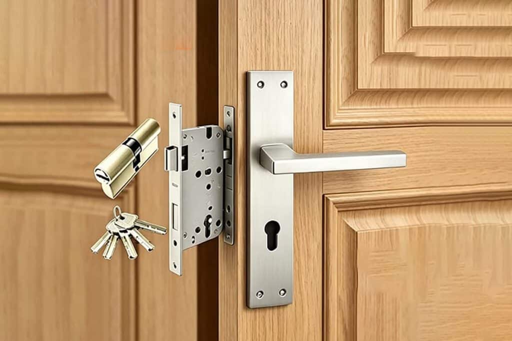
The lock case is the part that enters the door leaf. The forend is the front plate that sits on the door edge.10 Both parts affect machining. A door factory needs these sizes before it prepares the door pocket and front plate recess.11 I usually ask for a drawing because the case shape may include rounded corners, side projections, or different screw positions. A simple height and width is helpful, but it may not show all working details.
| Part | What I measure | Why it matters |
|---|---|---|
| Lock case height | Top to bottom of case body | It controls pocket height |
| Lock case width/depth | Forend side to rear side of case | It controls pocket depth inside the door |
| Lock case thickness | Side face to side face | It controls door thickness fit and clearance |
| Forend length | Top to bottom of front plate | It controls front recess length |
| Forend width | Left to right width of front plate | It controls edge recess width |
I always make a clear difference between case width and forend width. Some buyers call the case depth “width,” and some factories call the forend width “faceplate width.” This can create confusion. I solve this by marking the measurement direction on a photo or drawing. I also suggest checking the door leaf thickness. A lock body may fit the pocket, but the handle screws, cylinder length, and trim may still need the right door thickness. For project orders, I ask whether the door edge is wood, steel, aluminum, or fire-rated construction. This affects the preparation method. Any fire-rated or standard-specific requirement should be confirmed with the project documents and certificates, not guessed from size only.
Which screw and function details should I not miss?
I have watched small fixing details create big delays. The lock was correct in size, but the factory could not align the fixing holes.
I check screw hole positions around the follower and cylinder hole, often with a 38mm center distance, and I also measure latchbolt projection and follower size.12 These details help door factories prepare holes, assemble trims, and confirm smooth locking action.

Small dimensions do not always appear important in a quotation. They become important during machining and assembly. A buyer may approve the backset and PZ, then later discover that the screw hole position does not match the handle set or the door drilling jig. I have seen this happen when different suppliers use similar lock layouts but not exactly the same fixing points. So I include these details in my confirmation sheet.
| Detail | What I measure | Common note |
|---|---|---|
| Screw hole spacing near follower | Center to center of fixing holes | Often around 38mm, but I confirm |
| Screw hole spacing near cylinder | Center to center or hole to reference line | It must match trim or plate needs |
| Follower size | Square hole size | Commonly 8×8mm |
| Latchbolt projection | From forend face to outermost latch point | It affects strike plate contact |
| Deadbolt throw | Bolt extension distance when locked | I confirm if the project asks for it |
I measure latchbolt projection from the forend to the outermost point of the latch. This tells me how much the latch reaches into the strike area. I also check whether the latch is reversible if the buyer needs left and right door flexibility. I do not treat this as a replacement for project testing. I treat it as a practical check before order confirmation. For wholesalers, these small details are useful because their customers may compare locks by sample. For door factories, these details are more serious because production tools need fixed hole positions. A wrong screw distance can force manual rework, and manual rework can damage finish or slow down shipment.
What tools and habits help me avoid wrong lock measurements?
I believe many measurement errors come from poor habits, not poor tools. A lock on a tilted table can give a wrong reading fast.
I use a vernier caliper when possible, and I measure on a flat table. I keep the tool perpendicular to the forend. I measure centerlines, not hole edges. I also write each dimension with a clear name and unit.

A tape measure is useful for quick checks, but I prefer a caliper for sample review. The caliper gives better control on small details like forend width, case thickness, screw hole spacing, and follower size. I still use careful technique. A good tool does not fix a bad measuring angle. I keep the lock stable. I do not hold it in the air. I avoid measuring across curved or raised surfaces unless I know the correct reference point.
| Habit | How I do it | Result I want |
|---|---|---|
| Flat surface | I place the lock on a table | I reduce movement |
| Perpendicular tool | I keep the tool square to the forend | I reduce angle error |
| Centerline reading | I measure center to center | I avoid edge confusion |
| Clear unit | I write mm after each size | I avoid unit mistakes |
| Photo marking | I mark arrows on a lock photo | I avoid language confusion |
| Double check | I compare sample and drawing | I reduce order risk |
When I confirm an EN mortise lock with a buyer, I often ask for three things: the existing lock sample, the door preparation drawing, and the matching handle or cylinder information. If the buyer has only one of these, I can still help, but I need to mark the unknown points. This is the safer way. It is also the way I protect both sides from wrong production. Common sizes help me start the discussion. Exact measurement finishes the discussion.
Conclusion
I measure lock size by checking all working dimensions, not only the case, so the door, handle, cylinder, screws, and latch fit correctly.
"How to measure and choose the right mortise lock size - BlueID", https://www.blue-id.com/en/blog/mortise-lock-mass. Standards and technical guidance for mechanically operated locks identify dimensional relationships such as backset, spindle position, cylinder position, and faceplate geometry as parameters used to coordinate the lock body with door preparation and associated hardware. Evidence role: general_support; source type: institution. Supports: A neutral technical or standards source should show that mortise lock dimensions are reference points for door machining and hardware alignment.. Scope note: This would support the general compatibility mechanism, but not the author's specific factory experience. ↩
"Door handle - Wikipedia", https://en.wikipedia.org/wiki/Door_handle. Lock-hardware terminology defines backset as the horizontal distance from the door edge or lock face to the centerline of the lock function, supporting its use as the reference dimension for cylinder placement. Evidence role: definition; source type: institution. Supports: A standards glossary or institutional guide should define backset as the distance from the door edge or faceplate to the center of the lock or cylinder function.. ↩
"How to Measure a Door's PZ - YouTube",
. European lock-dimension references describe the PZ dimension as the center distance between the lever spindle or follower and the profile-cylinder centerline, which supports the article's definition of PZ. Evidence role: definition; source type: institution. Supports: A neutral lock-standard or technical source should define PZ as the distance between the spindle center and the cylinder center.. ↩"[PDF] DOOR HARDWARE (SCHEDULED BY DESCRIBING PRODUCTS)", https://fpm.usc.edu/wp-content/uploads/2021/11/087102-USC-HSC-door-hardware-Guide-Specification_1.pdf. Architectural hardware references explain that mortise-lock templates coordinate the lock case, spindle, cylinder opening, and trim locations with the prepared door, supporting the claim that backset and PZ affect multiple adjacent components. Evidence role: mechanism; source type: education. Supports: A technical education or architectural hardware source should explain that lockset templates coordinate lock holes, cylinder openings, spindle positions, and trim locations.. Scope note: Such a source would support the general design relationship, not every possible lock and trim combination. ↩
"DIN 18251: The German Standard for Mortise Locks - umaylocks.com", https://umaylocks.com/din-18251/. DIN/CEN-oriented dimensional references for mortise locks list nominal backset values including 45 mm, 55 mm, and 60 mm, supporting their treatment as common European options. Evidence role: general_support; source type: institution. Supports: A standards-based dimensional reference should show that these backsets are established nominal options in European mortise-lock practice.. Scope note: This would document common nominal values, but availability still depends on the lock type, manufacturer, and project specification. ↩
"[PDF] Distances Between United States Ports - NOAA Nautical Charts", https://nauticalcharts.noaa.gov/publications/docs/distances.pdf. European mortise-lock dimensional references identify PZ or center-distance values such as 72 mm, 85 mm, and 92 mm, supporting the article's examples of common lock layouts. Evidence role: general_support; source type: institution. Supports: A European lock dimensional reference should show that 72 mm, 85 mm, and 92 mm are recognized PZ or center-distance values.. Scope note: The citation would support the existence and common use of these nominal dimensions, not guarantee that they apply to all EN mortise locks. ↩
"Don't be confused – Lock jargon explained - Standfast Security", https://www.standfast-security.co.uk/dont-be-confused-lock-jargon-explained/. Architectural hardware glossaries define the follower as the lock component engaged by the spindle, commonly associated with the square spindle aperture for lever operation. Evidence role: definition; source type: institution. Supports: A hardware glossary should define the follower as the lock component or aperture operated by the spindle.. ↩
"M METERXITY 2-Pack Door Knob Spindle, 3 x 0.3 Inch - Amazon.com", https://www.amazon.com/METERXITY-2-Pack-Spindle-Replacement-Mortise/dp/B0F29FDTGC. European lock and lever-hardware dimensional references commonly specify an 8 mm square spindle interface for lever-operated locks, supporting the article's statement that 8×8 mm followers are common. Evidence role: general_support; source type: institution. Supports: A European lock or lever-hardware dimensional source should document 8 mm square spindle/follower use.. Scope note: This supports common practice, but exceptions may occur for special markets, functions, or product systems. ↩
"WC room door mortise lock - forend width 20 mm", https://www.sullus.com/kbv-wc-room-door-mortise-lock-forend-20-mm.html. European mortise-lock dimensional references list faceplate or forend dimensions in nominal sizes including widths around 20–24 mm and lengths around 235–240 mm, supporting these figures as common examples. Evidence role: general_support; source type: institution. Supports: A standards-based dimensional table or neutral technical reference should document common forend widths and lengths.. Scope note: The source would support these as common nominal dimensions, not as universal requirements for every lock model. ↩
"Hi group! I want to restore this door to a mortise lock but the ones I ...", https://www.facebook.com/groups/1706748102970911/posts/4192536391058724/. Architectural hardware references distinguish the mortise lock case, which is installed within the mortised pocket of the door, from the faceplate or forend, which is fixed along the door edge. Evidence role: definition; source type: institution. Supports: A hardware glossary or installation reference should distinguish the mortise lock case from the faceplate/forend.. ↩
"How to Cut a Door for a Mortise Lock | DIY Guide - danddhardware", https://www.danddhardware.com/how-to-cut-a-door-for-a-mortise-lock.html. Door-hardware installation references describe cutting the mortise pocket to accept the lock case and recessing the door edge to receive the faceplate, supporting the need to know case and forend dimensions before machining. Evidence role: mechanism; source type: education. Supports: A woodworking, door-manufacturing, or architectural hardware source should explain that mortise pockets and faceplate recesses are cut to match the lock body and faceplate.. Scope note: This supports the general preparation sequence; individual factory methods may differ by material, tooling, or certification requirements. ↩
"How-To Identify & Replace a Sliding Glass Door Mortise Lock",
. Door-hardware dimensional references include fixing-hole spacing, spindle/follower size, and latch projection among the dimensions used to coordinate lock bodies with trim and door preparation; some European layouts use 38 mm fixing centers. Evidence role: general_support; source type: institution. Supports: A lock or door-hardware dimensional reference should show that fixing-hole spacing is part of trim compatibility and that 38 mm spacing is a recognized layout in some systems.. Scope note: This would support the relevance and existence of the 38 mm layout, but not prove that it is used by all EN mortise locks. ↩